Wednesday, October 31, 2018
Week 9 Update
For this week I focused on sharpening up our presentation and trying to get some FEA to the Solar Panel Team. I found myself having several issues with the columns provided by Futran when I attempted to perform FEA. I am currently working with David to rebuild these so we can continue on with our analysis and get some information out to the Solar Panel Team.
For the next week, I am hoping to help out with CAD drawings and FEA on these so that we can continue to build material to present to the rest of the teams. We are currently focusing our attention on designing the junction and possibly implementing a different method of curvature. We are looking into welding straight sections to resemble a curve and then using a thin metal sheet to attach to the inside of the curve to smooth it out. This would be opposed to bending the tubing needed for the railing.
I am currently on schedule but am running a little late on the FEA for the column. This is just due to the bad CADs, so once that is fixed I can get that done too.
Wednesday, October 24, 2018
Week 8 Update
For this week I focused my attention on the second presentation we will be giving on 10/24 (Wed). This presentation was finalized after i performed some FEA on the four different kind of third rail designs. In the end, my partner and I decided to go with the hollow diamond shape; this shape is just a 2x2" square sheet metal beam that will be rotated 45 degrees to get the diamond shape (figure 1). The FEA that was conducted is pictured in figures 2,3 and 4.
 Figure 1 (left): Design for third rail
 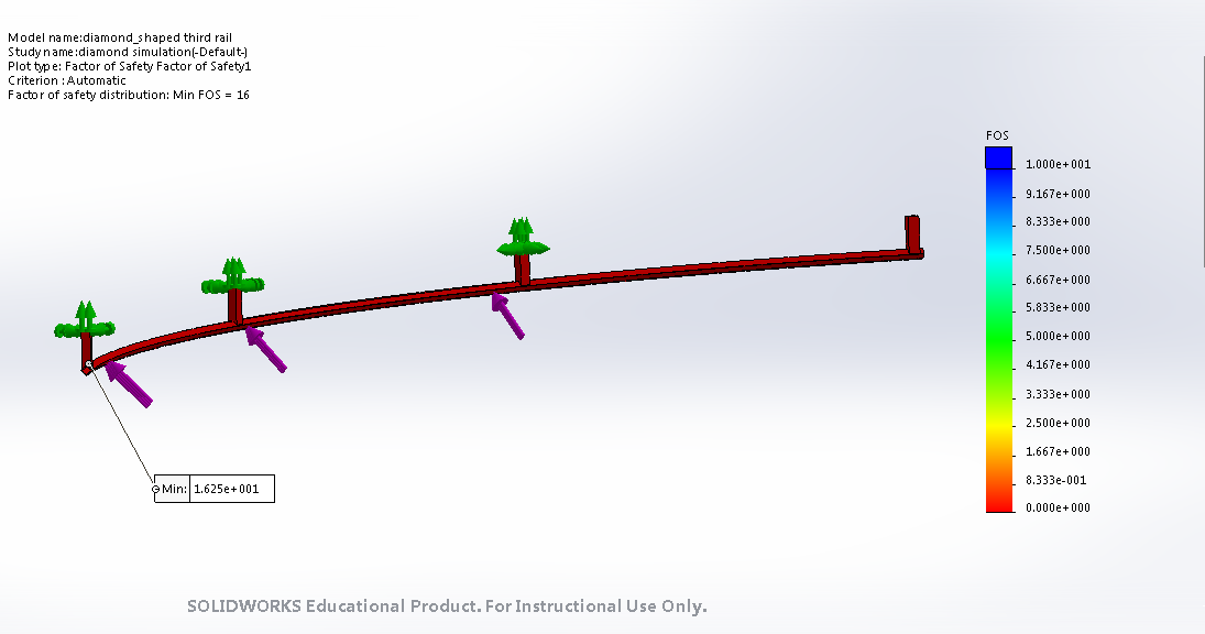 Figure 2 (left): FOS=16 for the hollow diamond-shaped rail
 Figure 3 (left): Highest displacement is 1.31mm
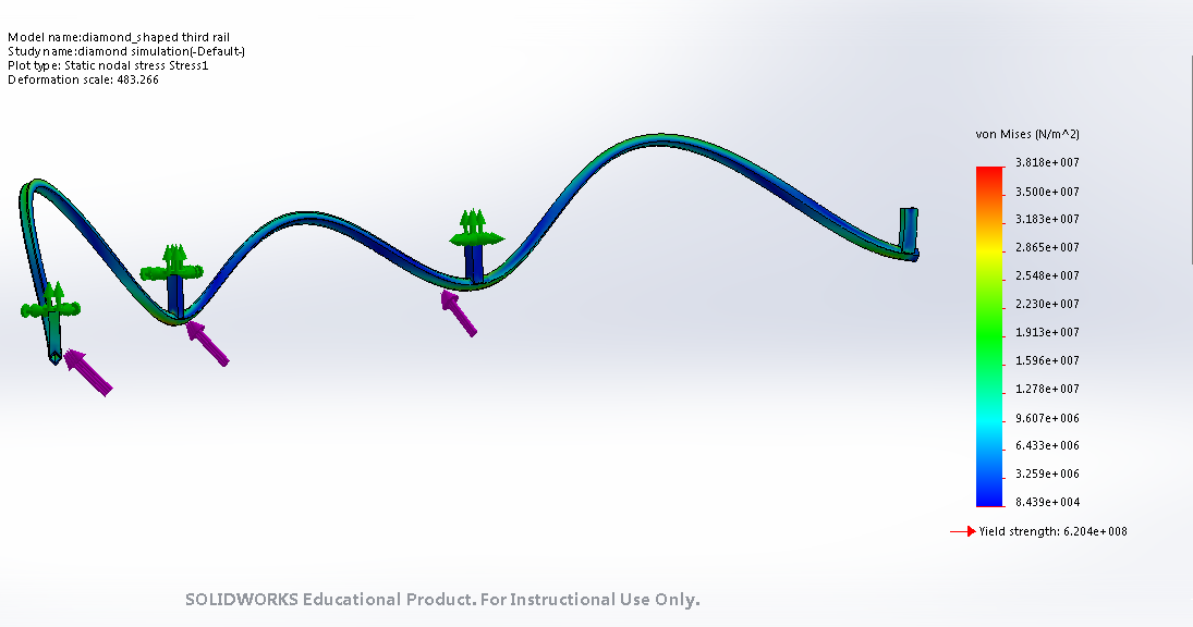
Figure 4 (above): the Von Mises stresses are presented with the highest being around 2.32e7 Pa
Wednesday, October 17, 2018
Week 7 Update
For this week, I focused on curving our track and implementing the third rail to get a conceptual design. This design was needed to add to our presentation next week, so I spent a lot of time trying to perfect that curve. Our design is not the best, but we wanted to at least have a representation for the presentation and also to show to other groups so they can have an idea of our design.
I also focused on the third rail system and am hoping to start some FEA on this so that we have more to talk about during the presentation. I am still familiarizing myself with ANSYS and SolidWorks FEA, so I am hoping to have that done before the weekend so that I am right on track for Presentation #2. As of now, we are going to be implementing the triangular third rail and that provides a flat surface for the supports to be welded onto (figure 1). We want our third rail to withstand flexing and the force that the bogie will be exerting onto it. I believe that using the triangular shaped third rail will help with these because the supports will be welded onto a flat surface versus being welded onto a triangular shape (figure 2).
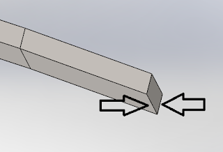 Figure 1 (left): The top of this rail is triangular
 Figure 2 (left): The third rail design we will be
I also focused on the third rail system and am hoping to start some FEA on this so that we have more to talk about during the presentation. I am still familiarizing myself with ANSYS and SolidWorks FEA, so I am hoping to have that done before the weekend so that I am right on track for Presentation #2. As of now, we are going to be implementing the triangular third rail and that provides a flat surface for the supports to be welded onto (figure 1). We want our third rail to withstand flexing and the force that the bogie will be exerting onto it. I believe that using the triangular shaped third rail will help with these because the supports will be welded onto a flat surface versus being welded onto a triangular shape (figure 2).
Figure 1 (left): The top of this rail is triangular Figure 2 (left): The third rail design we will be
implementing. The supports are also shown
Wednesday, October 10, 2018
Week 6 Update
For this week, I focused on possible designs for the third rail. I was trying to create an assembly to show what the third rail would look like implemented into Futran's design. Below, are two different examples for the third rail design (triangular or diamond-shaped). We are still debating if the rail should be solid or hollow as shown in images. If the rail is solid, we would be welding on the supports and if it is hollow, we would be bolting on the supports. Our decision for whether to go with solid or hollow will be made after we conduct some analysis. Also, the arrows in the images show where the bogie comes in contact with the rail.
I am still working on the assembly with the third rail implemented, and will hopefully have that done for the second presentation. We are hoping to also do some analysis on the third rail so that we can decide on what shape and if it should be solid or hollow.
Image 1 (left): Diamond-shaped solid cross section
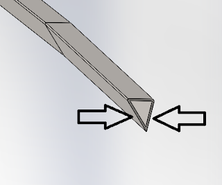 Image 2 (left): Triangular-shaped hollow cross section
I am still working on the assembly with the third rail implemented, and will hopefully have that done for the second presentation. We are hoping to also do some analysis on the third rail so that we can decide on what shape and if it should be solid or hollow.
Image 1 (left): Diamond-shaped solid cross section Image 2 (left): Triangular-shaped hollow cross section
Wednesday, October 3, 2018
Week 5 Update
For this week, we decided to focus on getting our dimensions for the different parts of the Guideway. We wanted to make sure that everyone on the Bogie teams could design accordingly. We were not able to get the files for each individual part of the track, but we were able to get some overall dimensions that other teams would need.
The next step is going to be implementing some designs. Our goal is to have the third-rail designed by next week so that we can start some analysis.
The next step is going to be implementing some designs. Our goal is to have the third-rail designed by next week so that we can start some analysis.
Subscribe to:
Posts (Atom)